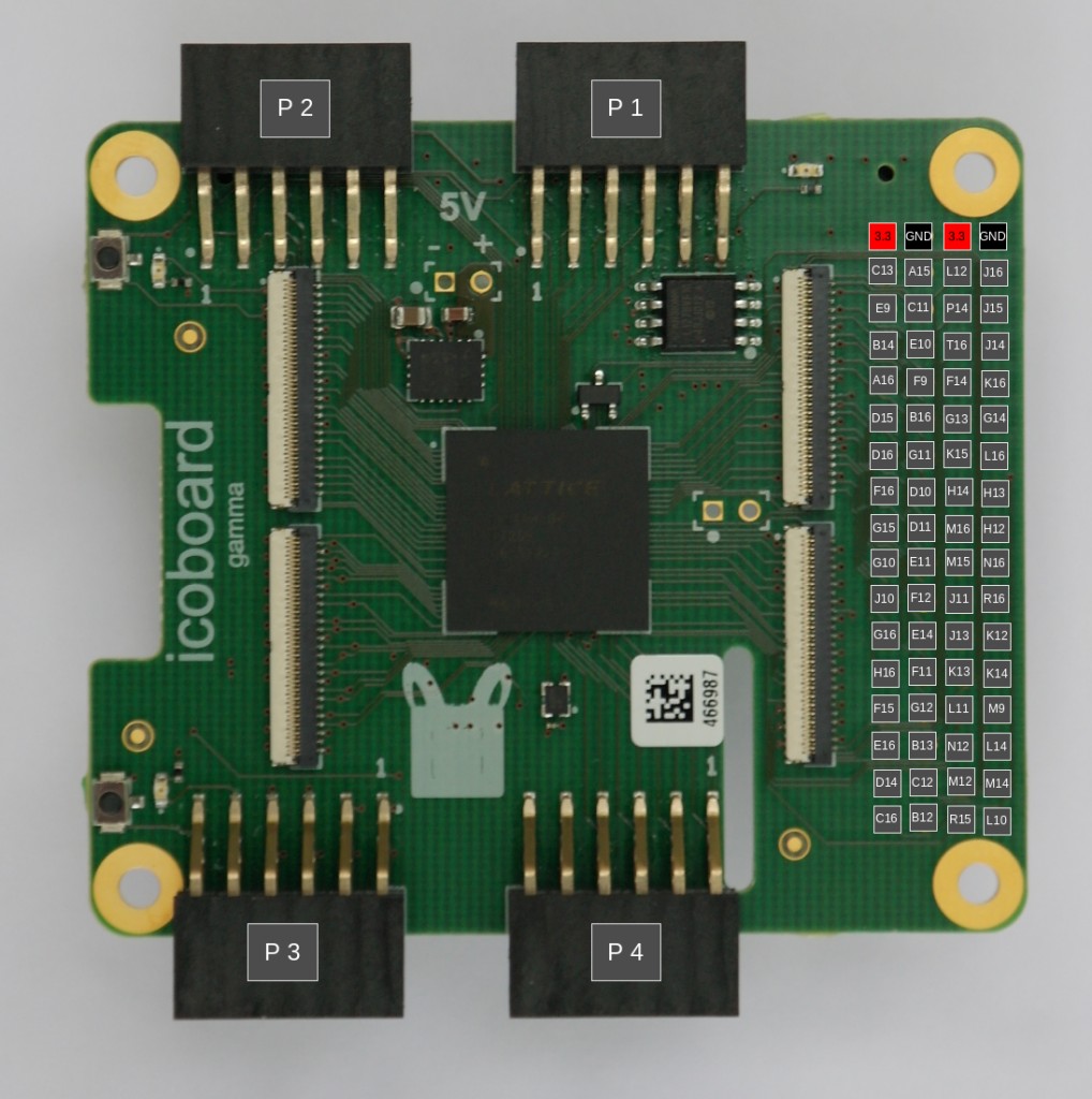
UART and GPIO on the PMOD connectors of the IcoBoard running a RISC-V core.
In an earlier post, we saw how to run a RISC-V core on an IcoBoard.
Today, we will see how to use the four PMOD connectors in two different ways: as normal GPIO pins as well as the Rx and Tx pins of a UART.
The PMOD connectors
There are four 12 pin PMOD connectors, labelled P1, P2, P3 and P4. The location of these connectors can be seen in this figure.
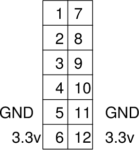
The location of pin number 1 is specified on the PCB itself. Pins 5,11 are GND and 6,12 are 3.3V.
Pin 1,2,3,4,7,8,9,10 are GPIO pins 0 to 7 on the RISC-V core.
LED connected to GPIO 0 of P1
[Download tar file containing sample code from here. Untar under icotools/icosoc/examples]
Let’s check out icotools/icosoc/examples/simple-gpio-pmod1/main.c:
#include <stdio.h>
#include <stdint.h>
#include "icosoc.h"

void delay()
{
    for (int i = 0; i < 100000; i++)
        asm volatile ("");
}

int main()
{
    int n = 0; // GPIO 0
    icosoc_ledstrip_dir(0xff);

    while(1)
    {
        icosoc_ledstrip_set(1 << n);
        delay();
        icosoc_ledstrip_set(0);
        delay();
    }
}
Here is a part of icosoc.cfg:
# enable compressed ISA support
compressed_isa


# LED on PMOD1
mod gpio ledstrip
  address 2
  connect IO pmod1
8 LED strip connected to P1
Numato Lab has an LED strip (with 8 LED’s) which we can connect to one of the IcoBoard PMOD connectors (say P1).
Here is the documentation regarding the LED strip.
This C code will cycle the LED’s on the strip one after the other (icotools/icosoc/examples/simple-gpio-8leds-pmod1):
#include <stdio.h>
#include <stdint.h>
#include "icosoc.h"

void delay()
{
    for (int i = 0; i < 1000000; i++)
        asm volatile ("");
}

int main()
{
    int n = 0;
    int pat[] = {0, 4, 1, 5, 2, 6, 3, 7};
    icosoc_ledstrip_dir(0xff);
    while(1)
    {
        icosoc_ledstrip_set(1 << pat[n]);
        delay();
        n = (n + 1) % 8;
    }

    while(1);
}
Here is a short video:
pmod-8led from Pramode C E on Vimeo.
UART Tx and Rx on P1
It is easy to configure the RISC-V processor with a UART. Here are the relevant lines in icotools/icosoc/examples/simple-serial/icosoc.cfg:
mod rs232 ser0
  address 1
  param BAUD_RATE 115200
  connect rx pmod1_1
  connect tx pmod1_2
We will now connect the Tx pin of a USB-to-serial converter to pin 1 of P1 and the Rx pin of the USB-to-serial converter to pin 2 of P1.
Let’s look at a C program which keeps writing a message repeatedly to the UART (icotools/icosoc/examples/simple-serial/main.c):
#include <stdio.h>
#include <stdint.h>
#include "icosoc.h"

int main()
{
    char buffer[100] = "Hello!";

    while(1)
    {
        icosoc_ser0_write(buffer, 6);
        for (int i = 0; i < 100000; i++)
            asm volatile ("");
    }
}
A Python program running on the PC receives the message and prints it out:
import serial

PORT='/dev/ttyUSB0'
BAUD = 115200

fd = serial.Serial(port=PORT, baudrate=BAUD)

while True:
    print fd.read(6)